Max cavity size and max cavity component count were offered as reports in the 16.5 release and are now available as DRCs in the 16.6 release of Allegro PCB Editor. Fab houses supporting embedded component manufacturing offer design guidelines on cavity usage.
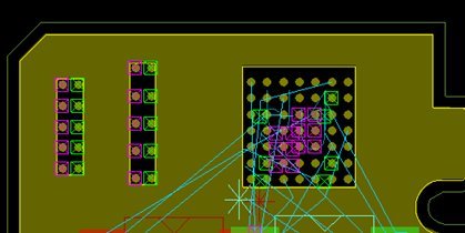
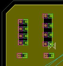
Consider a PCB with the following characteristics. Layer SIGNAL_7 is displayed where you see two merged cavities on the left as the result of Cap placement combined with embedded parameter record #2 (min cavity gap for merging). There is one large cavity on the right associated with the BGA:
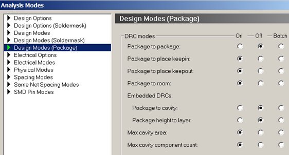
Select Setup – Constraints – Modes – Design Modes (Package) then enable the ‘Max cavity size’ and ‘Max cavity component’ count DRC mode:
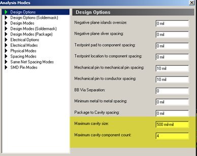
Open the Design Options form:
- Enter ‘3500’ for Max cavity size (units are sq mils)
- Enter ‘4’ for max cavity comp count
Close form and note DRCs in the Allegro canvas:
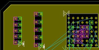
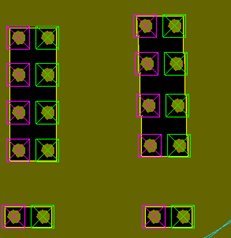
Both DRC types are applicable to the column of Caps while the BGA cavity is greater than the specified 3500 sq mils. Move 1 cap from each column downward. We've resolved the max count issue, but still have an area issue:
Compress the placement using the new Component Alignment features. (Equal or DFA spacing):
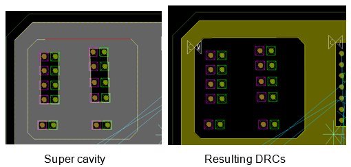
No action is required on resolving the BGA DRC. This might require an edit to the symbol definition to meet the rule. Manually draw a ‘super cavity’ around all 10 Caps. This is done using:
- Shape – Manual/Void Cavity
- Select Polygon
- Select any part of the yellow cavity shape
- Draw Polygon
New DRCs should be generated:
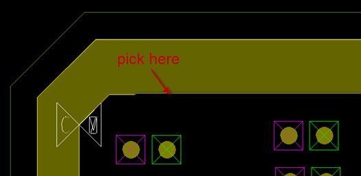
Delete the manually drawn cavity:
- Select Shape – Manual/Void Cavity
- Select ‘Delete’ from the pull-right menu
- Make a pick on the void outline of the cavity to delete it
I welcome your feedback!
Jerry “GenPart” Grzenia